Understanding metal interference in RFID and NFC systems
Deploying RFID and NFC tags near metal surfaces introduces immediate physical challenges that require careful planning. Conductive materials naturally disrupt the electromagnetic fields that these systems rely on to communicate, which often leads to frustrating blind spots and failed reads. However, this signal interference is a standard physical reality that you can manage effectively with smart layout choices and the right hardware configurations. Recognizing these environmental constraints early in your project empowers your team to implement reliable tracking solutions without unexpected delays.
How metal surfaces disrupt radio frequency signals
When you place standard tags against conductive materials, the physical interaction between the metal and the radio waves fundamentally alters how your system operates. Metal surfaces interact with electromagnetic energy in specific ways that actively fight against the communication loop between your reader and the tag. Understanding the mechanisms behind this disruption helps your team troubleshoot failed reads logically rather than relying on guesswork. We can break down this interference into three primary physical behaviors that you will encounter in real industrial environments.
Signal reflection and blind spots
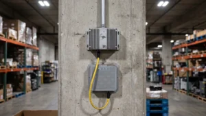
Metal behaves like an electromagnetic mirror for Radio Frequency (RF) waves, causing the signals emitted by your reader to bounce back into the surrounding space. When these reflected waves collide with the original incoming signals, they often create destructive interference that cancels out the energy entirely. This collision carves out physical blind spots in your facility where a reader suddenly drops communication just millimeters away from the tag. For NFC systems specifically, the metal generates an opposing magnetic field that starves the tag of the energy it needs to boot up.
Antenna detuning near metal
Every tag features an antenna that engineers have tuned to resonate at a very specific operating frequency. Placing a standard tag directly onto a conductive surface acts like an unintended ground plane, which drastically changes the electrical capacitance and inductance of that antenna. This proximity forces the resonant frequency of the tag to shift completely out of its working band, resulting in a massive impedance mismatch. Because the tag and the reader no longer operate on the same frequency, the power transfer drops to zero and the asset becomes virtually invisible to your system.
Shielding and absorbed energy
Metallic surfaces contain free electrons that move easily when struck by incoming radio waves, generating an induced electrical current on the surface of the material. As these induced currents rush back and forth through the resistive structure of the metal, they convert some of the vital electromagnetic energy into microscopic amounts of heat. This absorption process drains power away from the microchip before it can gather enough voltage to wake up and transmit its data back to the reader. Ultimately, this energy loss severely reduces the effective read range of your system and compromises the reliability of your tracking infrastructure.
Liquids and other challenging materials to watch out for
While metal presents the most obvious barrier to signal transmission, water and other liquid products also absorb a massive amount of radio frequency energy. Water molecules act like a sponge for Ultra-High Frequency (UHF) radio waves, soaking up the electromagnetic energy and converting it into heat before the tag can harvest it. This absorption leaves the tag with insufficient power to turn on, while uneven liquid surfaces and bubbles further scatter the remaining signal path. High moisture content or ionic solutions, such as saline or specific chemicals, pull away the induced current and lead to highly inconsistent reads across your facility.
Beyond liquids, dense composite materials like carbon fiber introduce their own complex layers of signal attenuation. The natural electrical conductivity of carbon fiber causes the material to reflect radio waves, while the specific orientation of the fibers can trap and dissipate the remaining energy internally. Recognizing these less obvious environmental hazards prevents costly blind spots during your initial deployment phase. By mapping out where your tags will encounter liquids or dense composites, your team can adjust placement strategies and maintain strong communication links throughout your entire operation.
Steps to mitigate interference during installation
Designing around physical constraints requires a concrete and sequential methodology that ensures reliable read rates in harsh environments. Walking through a structured installation process allows your team to identify potential hazards and adapt your technology to the existing infrastructure. You can systematically eliminate dead zones by testing signal behavior before you commit to a final hardware configuration. Following these specific steps will build confidence in your deployment and protect your project from unexpected technical failures.
- Conduct a comprehensive site survey: Map out all structural metals, storage racks, and machinery across your facility to identify where signal reflection will be highest. Deploy a portable reader to scan the ambient environment and test how radio waves bounce off nearby steel or concrete. This foundational step reveals exactly where you need to adjust your approach before you begin mounting hardware. Recording the exact locations of these physical barriers helps you establish clear and effective read zones.
- Optimize tag orientation: The alignment between your tag and the reader directly dictates whether the signal can successfully power the microchip. When dealing with standard tags near metal, ensure they protrude away from the surface like a flag rather than sitting flat against the conductive material. Maintaining an air gap prevents the metal from inducing secondary currents that cancel out your tracking data. If items pass the reader at random angles, ensure you account for these shifts during testing.
- Adjust reader power and polarization: Calibrate your reader power levels carefully, as excessive power near metal causes severe bouncing and ghost reads. Use antennas with circular polarization to maintain readability as tagged items shift angles past reflective metallic surfaces. Positioning your antennas at strategic angles minimizes direct bounce back and keeps your data collection stable. Documenting these configuration settings ensures your team can replicate successful reads across multiple checkpoints.
- Test physical standoff distances: Move a standard test tag around known metal pillars and racks to map where signal nulls or cancellations occur. Experiment with different non-conductive spacers to find the exact distance required to restore field stability. Physical testing directly on your unique assets provides the most accurate data for your final deployment plan. This empirical approach removes the guesswork from your installation and secures a high-performing tracking network.
Choosing the right tags and mounts for metal environments
When standard inlays fail against conductive surfaces, specific hardware modifications exist to overcome these physical limitations. Manufacturers engineer specialized equipment that fundamentally changes how the antenna interacts with the surrounding electromagnetic field. Equipping your decision-makers with the knowledge of these hardware variations ensures you procure the exact formats required for your operational constraints. Exploring the differences between integrated solutions and physical modifications will guide you toward the most effective setup for your assets.
Specialized on-metal tags
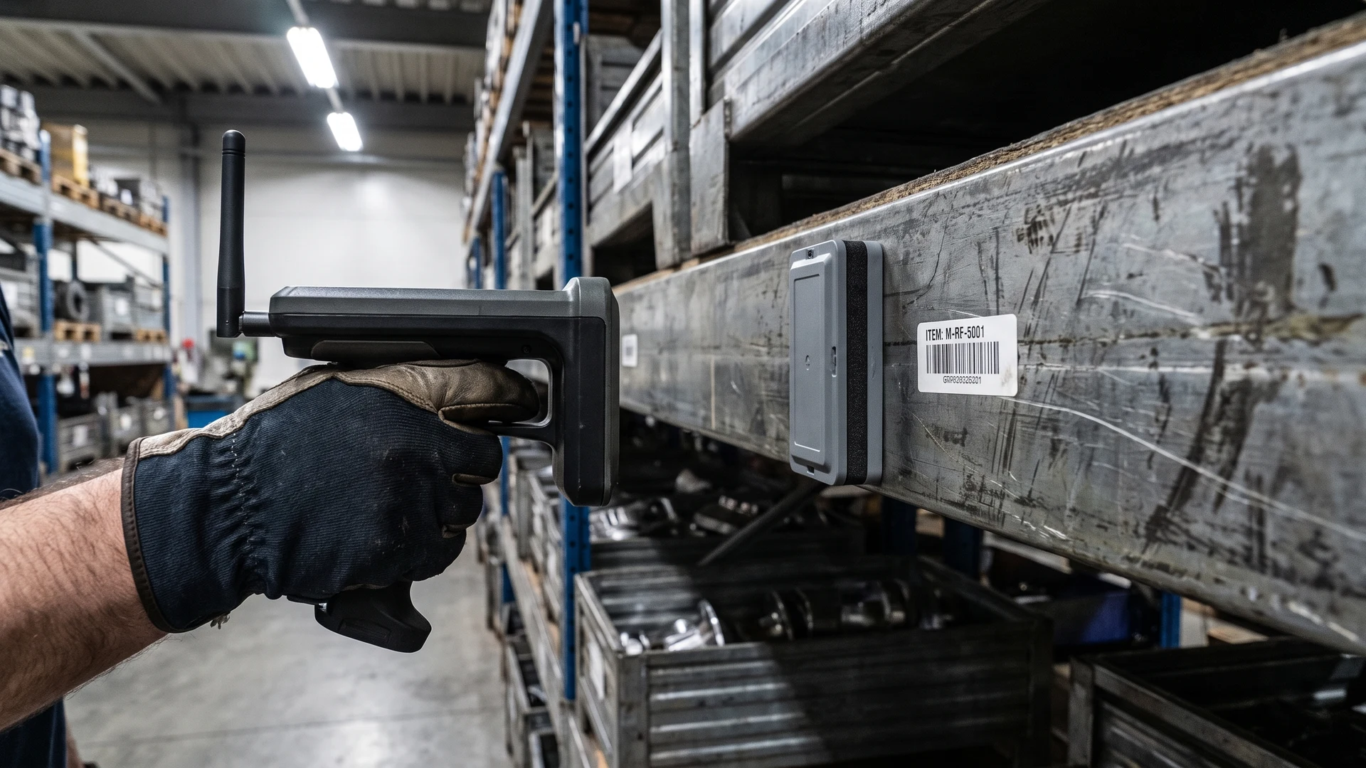
Specialized on-metal tags feature a thin layer of ferrite or magnetic shielding material positioned directly between the antenna and the adhesive backing. This vital ferrite layer acts as an electromagnetic buffer that isolates the loop antenna and absorbs stray fields to prevent disruptive currents from forming in the underlying metal. Instead of fighting the conductive surface, these precisely tuned tags actually leverage the metal backing as a ground plane to reflect and boost their own signal. Because they are housed in rigid plastic or ceramic casings, they also offer exceptional durability against the extreme temperatures and physical impacts common in industrial settings.
Spacers and physical standoffs
If you need to mount standard tags in a metallic environment, physical spacers provide a reliable way to prevent the surface from shorting out your radio signals. These standoffs are made from non-conductive materials like dense foam, hard plastic, or ceramic, which allow radio waves to pass through freely without any distortion. By physically separating the antenna from the metal surface, the spacer creates an essential electromagnetic buffer that minimizes the detuning effect. Maintaining this precise distance ensures the antenna couples properly with the reader, maximizing your data transmission accuracy while providing mechanical protection for the delicate microchip inside.
Planning for reliable reads from day one
Securing a successful rollout requires thorough environmental awareness and careful hardware selection long before your full deployment begins. By mapping out metallic infrastructure, accounting for liquid assets, and procuring the correct specialized tags, your team can eliminate interference issues proactively. The platform at RFID & NFC serves as a neutral educational resource to help you navigate these physical challenges and build a system that works reliably in your unique space. Taking a methodical approach to your installation leaves you fully prepared to capture accurate tracking data from the very first day of operation.
How much clearance does a standard tag need from metal?
Standard Radio Frequency Identification (RFID) tags need a small air gap from metal to avoid detuning. As a starting point, keep 0.2 to 0.5 inches of standoff using a non-conductive spacer. This limits eddy currents, the parasitic circulating currents in metal, and restores resonance. For flush mounting, use on-metal tags.
Can I use standard near field communication tags on metal?
Standard Near Field Communication (NFC) tags struggle on metal because the metal induces eddy currents that cancel the 13.56 megahertz magnetic field and detune the coil. Use anti-metal NFC tags with a ferrite layer that isolates the antenna and redirects magnetic flux, restoring stable energy transfer and reliable reads.
How should I orient tags near steel shelving to improve reads?
Near steel, orient the tag so the antenna is not flat against the surface. With Radio Frequency Identification (RFID), a flagged orientation that leaves an air gap reads better. Match the reader and tag polarization, meaning the wave field direction, or use circularly polarized antennas when angles vary.
How should I check a site for metal-related blind spots?
Start by mapping every large metal object, then define your critical read zones. Use a Radio Frequency Identification (RFID) reader to walk the space, note reflections and dead zones where tags drop out, and try reads. Adjust reader power, test circular polarization, which rotates field direction, and reposition antennas.
What frequency works best around liquids or metal-heavy areas?
For water-rich products or metal-heavy areas, Ultra High Frequency (UHF) Radio Frequency Identification can lose range due to absorption, detuning, and reflections. High Frequency (HF) at 13.56 megahertz or Low Frequency (LF) is more tolerant but offers shorter range. When long range is required, use on-liquid or on-metal UHF tags.